|
|
| In CyberMotion you can choose between three rendering algorithms for depiction, which have big differences in the underlying technology and picture quality.
|
| The scanline method is by far the simplest method and best suited for fast animation previews. Raytracing offers high quality and can simulate real world phenomena like mirror reflections, refractions in transparent objects and shadows. Above all stands the Global Illumination algorithm. The implemented photon mapping technology combines the pros of raytracing - reflection and refraction - with the ability to render also the indirect illumination caused by diffuse reflections in the scene.
|
|
|
| · | Scanline
|
| · | Raytracing
|
| · | Global Illumination - Raytracing and Photon Mapping
|
|
|
|
|
| The scanline algorithm scans the monitor screen line by line. Each line corresponds to a so-called scanline. These scanlines are now compared with the coordinates of the individual facets projected onto the screen and any intersections are calculated. If two facets overlap at the intersection-lines on the screen, the distance from the camera of each point of each line is calculated. The point closest to the camera is then drawn. This algorithm enables objects that overlap each other to be represented correctly. This procedure renders very rapidly in comparison with the raytracing algorithm. However, certain photo-realistic effects, such as true reflections, shadows or refractions through transparent objects cannot be rendered using this procedure. Transparency will be correctly depicted but refractions, e.g. the magnification of a magnifying glass, can only be calculated with Raytracing.
|
|
|
|
|

|
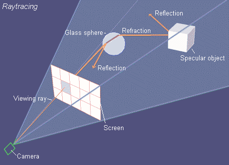
| In nature, a light-ray that leaves a light-source, reflects off different objects and then falls, sometime later, into the eye. Raytracing is exactly the reverse process. A "viewing ray" is sent out from the camera-viewpoint, through a projection-plane (the screen) and then tested for an intersection with an object in the area. If an intersection occurs the relevant pixel of the screen - at the point where the viewing ray passes through the projection-plane - can, therefore, be drawn in the calculated surface-intensity of the object. The viewing ray can also be followed further, however. At a mirroring object the angle of reflections is simply calculated and a new ray started searching. The surface intensity for the first object met then comes recursively from the incident light in addition to the light reflected from the other objects that are met.
|
| With this algorithm it is also possible to calculate the split in the viewing rays that is necessary with transparency. In order to render transparency realistically the surface-reflections are calculated from reflections in addition to the intensity of the light coming from behind. A mirror-ray and simultaneously a split viewing ray is calculated. If these viewing rays meet another transparent or mirror object, the whole process is started again, so the color for rendering only a single screen-point results from a whole collection of viewing rays.
|
| The recursion levels for reflections and split rays can be entered separately to keep the rendering time within reasonable limits.
|
|
|
| Raytracing - Parameters
|

|
| Almost all settings in this box only influence the depiction of the picture in raytracing mode. The only exception is the <Transparency>-button. With it you can switch transparency on or off for depiction in Scanline Mode too.
|
|
|
| Shadow - Select this button if you wish the picture to include shadows in the rendering.
|
| When calculating the light intensity for a surface, then first a light ray from the surface point to the light source is checked to see if there are any objects - or the object's own facets - between the light-source and the point being rendered. If there is, the calculation is broken off for this particular light source. If a transparent object casts a shadow then the light color is filtered by the objects surface color.
|
| Rendering time increases greatly with each light source, especially if soft shadows with multiple shadow sensors are calculated. Therefore, you can decide for each individual object if it does cast a shadow by using the <No Shadows> function in the material dialog. For convex objects , also switch on the <Convex> button in the material dialog to reduce rendering times (objects with a convex body shape do not cast shadows on their own surfaces). Furthermore, the shadow-calculation can be switched off for each light-source using the option <No Shadows> in the light dialog.
|
|
|

|
| Multiple Shadow-Sensors - Switch on this option if you want to generate a soft-shadow effect. Standard light sources like the lamp, sun and spotlight are defined with a specific radius. With it, instead of originating from a single point-light-source, the light comes from a spherical area light-source. For each light type you can enter a number of shadow-sensors in the light dialog. If this value is 1, a completely normal hard-edged shadow is rendered. If you use a value greater than 1 (say 21 for example), that number of shadow-sensors are used to scan the area of the spherical light area to determine, how much of the light-sphere is hidden by other objects. The results of the shadow-sensor evaluations are interpolated so a soft shadow is rendered.
|
| If the radius of a light source is very high and the number of shadow-sensors low, for example, it produces the effect of several light-sources standing close to each other. The greater the number of shadow-sensors and the less the radius then the better will be the soft shadow effect. The number of additionally calculated shadow-sensors should be kept as low as possible due to the rendering time required. In the forgoing example-picture the shadow was rendered with 9 shadow-sensors and a sun-radius of 40.
|
|
|
|
|
| Transparency - Transparent objects will be calculated with real refractions. The maximum number of retraces can be entered from 1-25 - as with the reflections.
|
| You can render transparencies even in scanline mode, but the depiction differs entirely from the results you achieve with raytracing. By tracing of refracted rays in the raytracing mode you can display a physically correct representation of refraction in transparent materials, whereas in scanline mode only a simple check is carried out to determine whether a point lies behind the transparent point. If it does, this point is simply filtered through the transparent object.
|
|
|
| Antialiasing smoothes such effects. With it, each screen pixel to be rendered is divided into several smaller sub-pixels and a search ray is calculated for each sub-pixel. An average intensity for the screen-point is then calculated from the intensities of all sub-pixels.
|
| Steps that depart slightly from the actual line are now plotted using the averaged intensity and altogether the impression of a somewhat blurred but more representative line is produced.
|
| The quality and with it the number of sub-pixels to be calculated can be set from 1-4:
|
| · | 1 = 4 sub-pixels
|
| · | 2 = 9 sub-pixels
|
| · | 3 = 16 sub-pixels
|
| · | 4 = 25 sub-pixels
|
| Antialiasing is only applied to certain pixels so the rendering time does not also rise by 4, 9, 16 or even 25- times because so many more pixels are calculated. It is only those pixels that deviate in their color-value by a threshold value from that of their neighbors that are subdivided into smaller pixels. This threshold value can be set via the corresponding parameter in the raytracing box. It is also possible to set this value to zero, thus every single pixel will be subdivided into sub-pixels and rendering time increases considerably. This should only be applied for a last high quality rendering, for instance, when severe antialiasing effects arise. Don't forget to reset the value afterwards to a common value about 0.8.
|
|
|
| Negative Antialiasing - A negative value (-1) can also be input for antialiasing. In contrast to calculating additional intermediate pixels for positive antialiasing, negative antialiasing departs from this process. Instead of more pixels, only half the pixels to represent the rendering are calculated. The color-values for those pixels that are not calculated are interpolated from the surrounding pixels, so that halving the calculation resolution does not reduce the resolution too severely.
|
| Advantage: Up to 200% speed-gain. In this way it allows a lot of quick control-pictures to be calculated and the alignment of shadows, reflections and illumination to be checked.
|
|
|
|
|
| Raytracing is a standard for high picture quality and for realistic reflections and refraction. One of the major drawbacks in a general raytracing implementation is that it does not take into account the indirect illumination - the light that is reflected from other objects in the scene other than the direct light from a light source. Usually a constant light intensity can be defined to simulate this indirect lighting but that is a very poor approximation. Escpecially in architectural scenes the illumination in a room is dominated by indirect light reflected many times from the diffuse sufaces in a building. With the photon mapping algorithm, CyberMotion provides a global illumination model that combines the pros of raytracing - reflection and refraction - with the ability to render also the indirect illumination caused by diffuse reflections in the scene.
|

|
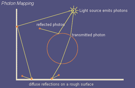
| Rendering a picture with photon mapping is a two pass procedure. In a preliminary run little packages of energy (photons) are emitted from the light sources in the scene. Similar to ordinary raytracing the path of this photons is traced through the scene and the distribution of photons is saved in a three-dimensional data structure called the photon map. After the photon map has been calculated the picture is rendered in an ordinary raytracing run and the photon map is evaluated when calculating the incoming light intensity for a point.
|
| There are more advantages of photon mapping:
|
| · | Color bleeding - for instance, when a green wall casts greenish reflections on a neighbouring white wall.
|
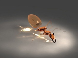
| · | Caustics - Caustics are light reflecions from highly specular surfaces or, e.g., the light gathered in a focal point after transmission through a glass lense.
|
|
|

|
| Example for caustic light reflections beneath a little glass figurine
|
|
|
| For a deeper understanding of photon mapping see also:
|
| Photon Mapping - Introduction and examples
|
| Light Dialog - Photon Emission Parameters
|
| Material Dialog - Photon mapping object properties
|
|
|
| The Photon Mapping Parameters for the Evaluation Process in the Raytracing Pass
|

|
| You can make use of photon mapping in two different ways:
|
|
|
| Only Indirect Illumination - Only the diffuse indirect light that has been at least once reflected in the scene is evaluated from the photon map. Then the incident light coming directly from the light source is calculated and combined with the indirect light.
|
|
|
| Global Illumination - All the illumination in the scene is calculated by evaluating the photon map only. You can read about the pros and contras in the chapter - Photon Mapping - Introduction and Examples.
|
|
|
| Static Photon Map in Animation - The photon map will be calculated only once at the beginning of an animation. You can use this option to animate a fly through an architectural scene where the objects themselves do not move. It is also possible to exclude individual objects from the photon mapping process - those will be illuminated only with direct lighting - and then you can even render animations with a static photon map and moving objects, e.g. a car driving through a street lined with houses.
|
|
|
| Photon Pool - For a good estimation of the incoming irradiance for a point on a surface a specific number of photons scattered around that point have to be gathered in the so called photon pool. The maximum number of photons to search for the photon pool determines the quality, sharpness and of course the rendering time. You should take into account that searching through a photon map that might hold millions of photon entries is not really a trivial thing. Appropriate values for the photon pool size lie between 250 and 800 photons when photon mapping is applied only for the indirect lighting, and 500 up to 5000 photons, when Global Illumination mode is activated with photon maps containing several million photons. As a rule you can say, the more photons in the photon map the more photons should be gathered in the photon pool, otherwise the pictures become a somewhat spotty appearance. For examples refer to the chapter - Photon Mapping - Introduction and Examples.
|
|
|
| Caustics - Light Reflections - Includes the calculation of caustic light reflections in the photon mapping process. Caustic photons are saved in a separate photon map, the so-called caustic map. This is due to the varying demands for global photons (soft indirect light) and caustic photons (sharper contours created by specular reflections and transmission).
|
|
|
| Caustics Pool - For the caustics pool you do not need as much photons as for the global photon pool. Caustic reflections often have sharp contours (e.g. light transmitted through a lens and focused in a sharp focal point) and with to much photons the caustic reflections would become to blurry. Good values lie between 80 and 250 photons, depending on the number of photons contained in the caustic map.
|
|
|
| For more examples see also:
|
| Photon Mapping - Introduction and Examples
|
| Light dialog - Photon Emission Parameters
|


